I have recently moved the blog over to the Hexo blogging engine.
Generating a MicroBlaze soft processor with ISE WebPACK 14.7
Xilinx provides a limited feature-set version of the MicroBlaze Soft Processor in the ISE WebPACK. The MicroBlaze allows for much higher level development tasks to be completed with ease. In the following I will show you how to setup a basic MicroBlaze project.
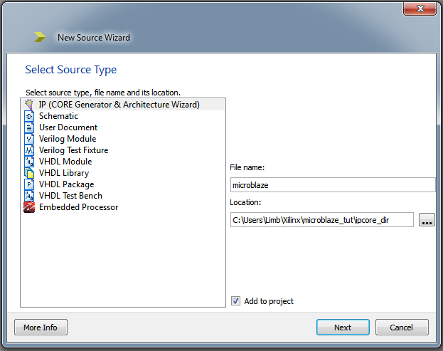
Begin by opening the ISE Project Navigator and creating a new project, ensuring you choose the correct settings for your specific device. VHDL or Verilog does not make a difference so feel free to pick what you are comfortable with. Right click on your device in the project hierarchy and click ‘New Source…’. Select ‘IP (CORE Generator & Architecture Wizard) as the type, and give it a file name.
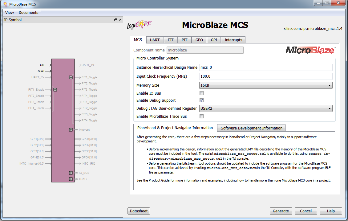
Select ‘MicroBlaze MCS’ from the Embedded Processing -> Processor subfolder and click next and finally finish. After a few moments the MicroBlaze generator will have appeared. It is within this window that we can choose all features we want to enable for our processor. It is important to ensure that you only enable features you need as each option will take up precious space on your design. It is also important that you remember the ‘Instance Hierarchical Design Name’ as we will need it later (in the picture below it is mcs_0). Go ahead and set the Input Clock Frequency to match that of your board, increase the Memory Size to 16KB and Enable Debug Support if you are so inclined.
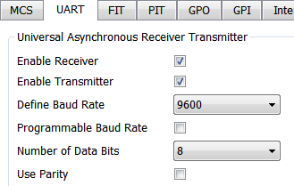
For this example we will create a processor that will increment a byte by 1 every second, and output the value via UART and onto a set of LED’s. To do so we must go to the UART tab and click ‘Enable Receiver’, ‘Enable Transmitter’ and set the Baud Rate to whatever value you would like.
Next click the FIT (Fixed Interval Timer) tab, and click ‘Use Timer’ for FIT 1. Since we will be using this timer to create a millisecond delay feature, you’ll want to divide your clock by 1,000 to get the appropriate value. In my case my NEXYS 4 has a 100 MHz clock signal, so I would divide 100,000,000/1,000 = 100,000 to get my desired value. We’re also going to need the interrupt, so clic ‘Generate Interrupt’.
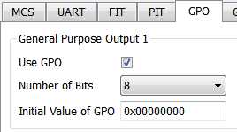
Finally click the GPO (General Purpose Output) tab, click ‘Use GPO’ for GPO 1, and set the number of bits to 8 (thus creating a 8 bit wide output port).
Click generate and ISE will begin to generate your processor. This process will take a few minutes so give it time to complete.
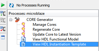
We now need to create a top file to instantiate our processor. Right click again on the project hierarchy and click ‘New Source…’ click either ‘Verilog Module’ or ‘VHDL Module’ and give it a name such as ‘microblaze_top’. ISE creates a HDL instantiation template we can insert into our top file, saving us a good amount of work. Click on the MicroBlaze xco file in the project hierarchy, and then in the window below expand ‘CORE Generator’ and double click ‘View HDL Instantiation Template’. This will open a window which will contain code similar to the lines below:
1 | //----------- Begin Cut here for INSTANTIATION Template ---// INST_TAG |
Copy this code and insert it into your top file. You can omit assigning signals to the FIT1 Interrupt and Toggle, as well as INTC_IRQ in this example since we will not be using them outside of the processor. Be sure to change ‘your_instance_name’ to the value you wrote down when generating the core (mcs_0 in this example). Your complete code should look similar to the following:
1 | module microblaze_top( |
At this point you’re going to want to generate a constraints file to map your I/O to sites available on your chip. We the need to execute a tcl script to setup the MicroBlaze so it is properly included in our synthesis. If you do not have the tcl console already open, click View -> Panels -> Tcl Console. Then type the following into the console:
1 | source ipcore_dir/microblaze_mcs_setup.tcl |
You should get output similar to the following:
1 | microblaze_mcs_setup: Found 1 MicroBlaze MCS core. microblaze_mcs_setup: Added "-bm" option for "microblaze.bmm" to ngdbuild command line options. microblaze_mcs_setup: Done. |
You’ll now want to implement the design by clicking the top file in the project hierarchy and in the list below right clicking ‘Implement Design’ and finally clicking run.
After your design is sucessfully implemented, it’s time to begin coding our processor. Open the Xilinx Software Development Kit application. When prompted for a workspace create a new folder called ‘workspace’ inside the folder of your ISE project and choose it. Close the welcome tab in the SDK window if it opens and you will now be sitting at the project interface. Click File -> New -> Application Project. Give the project a name, such as ‘microblaze_app’. Under Target Hardware, click the Hardware Platform drop-down and click ‘Create New’.
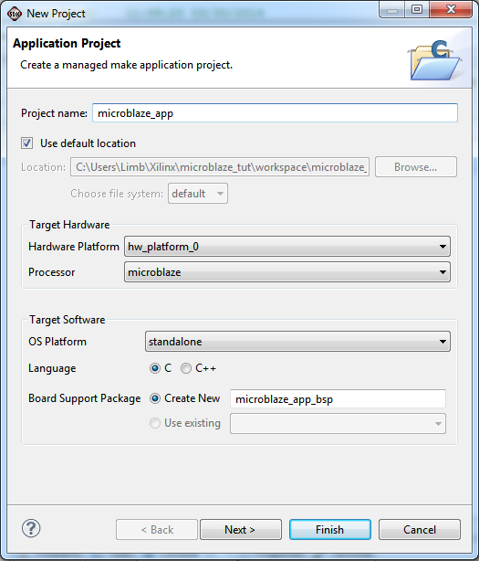
When the New Hardware Project window opens, click ‘Browse’ under Target Hardware Specification and browse inside the ipcore_dir of your project. Inside you will see a file named similar to ‘microblaze_sdk.xml’, select this file and click ok. Click finish to return to the New Project window. Ensure that our new hardware platform has been selected, the OS Platform is ‘standalone’, the Language is ‘C’ and ‘Create New’ is selected for Board Support Package. If all these are correct click next. Select ‘Hello World’ from available templates and click Finish.
The project will compile and you will have three new folders in the Project Explorer. Double click on the folder with the name you gave the project, such as ‘microblaze_app’, expand the src folder and double click ‘helloworld.c’. Here you will see the code that was generated. Modify the code so that it is similar to the code below:
1 | #include <stdio.h> |
Save the file and if the code does not auto compile, click Project -> Build All from the top menu. There is one last command we need to run in the tcl console to include our elf file we just created in our bit file. Go back to ISE and run the following command in the Tcl Console tab (change the values to the appropriate names if needed):
1 | microblaze_mcs_data2mem workspace/microblaze_app/Debug/microblaze_app.elf |
Which should generate the following output:
1 | microblaze_mcs_data2mem: Found 1 MicroBlaze MCS core. microblaze_mcs_data2mem: Using "microblaze_app.elf" for microblaze microblaze_mcs_data2mem: Added "-bd" options to bitgen command line. microblaze_mcs_data2mem: Running "data2mem" to create simulation files. microblaze_mcs_data2mem: Bitstream does not exist. Not running "data2mem" to update bitstream. microblaze_mcs_data2mem: Done. |
Right click ‘Generate Programming File’ in the Design window and click run to generate the bit file needed to program the board. Upon uploading to the board, you should see the LED’s incrementing every second to the corresponding value in binary. If you connect to the UART pins, you will also see the current value in decimal being printed every second.
An Adventure in Electronics: Building a Bus Pirate V4
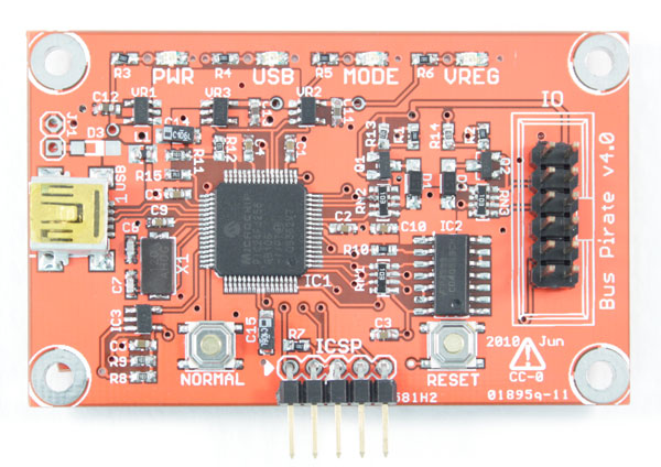
I had recently been on the hunt for useful tools to add to my workbench, when I came across Dangerous Prototypes Bus Pirate. This handy little device allows you to easily communicate with chips of all kind through various supported protocols, sniff SPI and I2C communication, program AVR’s and a whole bunch of other awesome stuff.
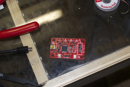
The folks over at Dangerous Prototypes are currently in the process of releasing a new version of the Bus Pirate, v4. With this new version, they did all sorts of nice improvements, mainly upgrading to a PIC24FJ256 microcontroller for extra room to add new features. Having decided I wanted one of these awesome gadgets I headed over to Seeed Studio to get one. Annnnddd… out of stock, bummer. But by chance I happened to stumble across a forum post by user schazamp who had set out to order a set of v4 PCB’s compatible with the Sick of Beige case. Two minutes later I had sent him $10 for two of the boards.
A couple days later and I had the boards in hand. Now being the foolish dope I am, I took the supplied mouser cart from the BP v4 wiki and after having to find a replacement for the now discontinued 3.3 volt LOD voltage regulators in the cart, I sent my order and waited. This was mistake number one. I was so excited about this that I didn’t even bother to match up the BOM (Bill Of Materials) against the cart. I was short quite a few pieces. The cart had the LED’s but the required resistors weren’t there. PNP Transistors? nope forgot those too. CD4066 IC? Nope wasn’t in there either. Lesson one: Don’t take things for granted, make sure you double check things yourself. Of course I only realized I was missing these parts way into my journey, so let’s continue.
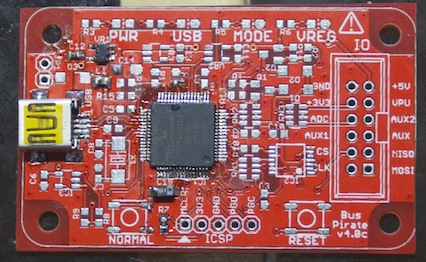
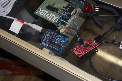
PCB’s and components in hand, I set out to build my first real SMD device. The closest I had gotten before was a HTTSOP TLC5951 chip, which with some solder wick was no problem. Following the wiki, I wired up the bare minimum to get the PIC chip working. Being an AVR chip guy, I didn’t have a PIC programmer lying around. Luckily for me, Fezoj on the forum had written some nifty code for using an ATMega8 to program the v3’s pic24 chip. This is where I ran into problem numbers two and three. As with all code, another user tried to make improvements to the AVR code. They seemed right to me, but they weren’t (as far as I could tell) tested code changes. But seeing as how they looked good to me, I went ahead and modified the code to work with a ATMega168/328 (which mostly meant adding a “0” to the appropriate code for the UART). I then uploaded it to a spare arduino, and hooked it up to the PIC. It didn’t work, I got a device ID of 0xFFFF which shouldn’t exist. I tried everything. I took out the chip and put it on a breadboard with 3.3 volt supply and everything but nothing worked. Wonderful.
I spent about 6 hours messing around with it to get it work. Maybe my 328 wouldn’t work. Maybe it would work on a 168. No good. I finally gave up and went to bed. The next morning I went back at it. Only this is when I should have started to go on the forums or IRC and ask for help. But I didn’t. That’s lesson number two: Ask for help instead of doing the same thing over and over. An hour or so in, I figured maybe this untested code was wrong. So I downloaded Fezoj’s original code and modified it for the 168/328 UART, uploaded the code and plugged it in. Something was different this time! It was reading a device ID finally! Excited I loaded the Bus Pirate bootloader (which was smaller and thus would take less time to upload then the whole firmware) into the upload program and had it write the code. 20 minutes later and it was done. I took my new pride and joy, and plugged it in… only for no com port to show up. I wouldn’t be able to upload the firmware if I couldn’t talk to the device. Maybe it messed up along the way, so I reloaded the bootloader. Nothing again. Repeat this several times with various troubleshooting ideas. And still nothing.
Finally I decided to look at the PDF Fezoj posted on how he came up with the code to program the PIC. Comparing the device ID’s listed in the PDF to what I was getting, I realized what I had wasn’t in the PDF. Ha! That there was the problem! Clearly either the program, or the AVR, or heck even the PIC was messing something up. Only, that wasn’t the case. The PDF I was reading didn’t have the device ID’s for the PIC24FJ256 series. I hadn’t even bothered to look at the device names in the sheet because I was just so frustrated. Lesson number three: Make sure you are looking at the right information in the right frame of mind.
It was about this time I decided that it was most likely the fact that this code was written for an ATMega8 and I was fubaring it by trying to get it to work on my 328/168. So I caved in an ordered an ATMega8 from mouser along with some crystals and ceramic caps I wanted to add to my toolbox anyway and went to bed.
The next day, running out of options I finally decided that maybe by having only the bare minimum circuitry hooked up, I could only talk to the chip via ICSP. Maybe I needed the crystal and all that hooked up. So I soldered all the parts I had ordered on… and realized I didn’t even have the capacitors for the crystals. A large portion of the components were on, and with the exception of the capacitors it should work. So like an idiot I soldered on two through-hole caps onto the SMD pads. Lesson number four: Patience is a virtue, and if you try and fit a square peg through a round hole… you’re going to end up breaking something. I ended up ripping off one of the solder pads for a capacitor, but luckily that happens at the end of the story.
Taking my frankenstein beast I gave it one last go and plugged it into the machine. Thinking to myself “It was definitely because the PIC didn’t have its external crystal, it’s going to work now!”, I plugged it in and again got.. nothing. I just couldn’t win. I caved in. I placed a second follow up order on mouser for the missing components (along with one resistor that I lost while holding it in my tweezers) and a PICKIt to program the chip. I paid 12 dollars in shipping for two different orders in less the 24 hours. Lesson four: Don’t place an order until you’re absolutely certain you’ve got everything you need, and don’t do it on the fly.
Defeated I decided what the hell, I’d load the entire firmware onto the chip and see what happened. An hour or so goes by, and it finally finishes. I plugged it in expecting nothing and to my surprise there it was. I finally got it to work. The programmer had been working the entire time. There was never anything wrong with the PIC. Later I realized while looking at the PDF for using ICSP on the PIC24FJ256 series, the device ID had been correct all along. If I had simply sat down and cleared my mind, or asked others about my problem I probably would’ve been done yesterday and not had ordered the ATMega8 or PIC programmer I no longer needed. I felt like an idiot. I felt like an even bigger idiot when I ripped off the pad for the capacitor after finally getting it to work. But that was easily fixed with a little wire jumper.
The next day came and I received the other missing components. I soldered the rest on (except for one chip, the CD4066 which I ordered in the wrong package size… be diligent!) and thats where I learned the last lesson of today: SMD LED’s and well, all components, still have to be oriented properly. I soldered them all on backwards because I was excited to finish my little bus pirate. That was pretty stupid. Luckily I made sure to check the orientation of all other parts before soldering them. But at least now I have a working bus pirate! (Except for the CD4066 which is coming in from digikey).
I hope if you’ve read this far and you are just starting out in electronics that you’ve learned something and won’t make the same stupid mistakes I did. Granted if this was a more serious project I definitely wouldn’t have been so arrogant and un-thorough as I was with this project, but sometimes we just get stupid. I will definitely take my time from now on and do things right. This was my first time assembling an SMD device, sourcing parts for something I wasn’t building, and using a PIC.
I feel like new doors have opened for me. SMD doesn’t look nearly as daunting as it once did. I now know how to use a BOM. I learned some very important things along the way. Perhaps sometime I’ll get around to making that second Bus Pirate, and this time I’ll know what I’m doing.
Hello, World!
First post for the blog. Nothing to see here, move along.. move along.